Router Redundancy with VRRP

In a previous article, we touched on the problems of redundant network infrastructures and looked at how MC-LAG technology works. Today, we’re going to talk about a more complex, but reliable, technology that enables redundancy at the data center level. What we’re talking about here is boosting router availability using VRRP (Virtual Router Redundancy Protocol).
The information in this article should be useful for people looking to ensure that their Internet resources are always available, but who don’t have the technical abilities to do so—they don’t have their own autonomous systems, IP address blocks, or BGP connections to providers.
Choosing a Backup Plan
Let’s say we have a mission critical resource that must always be available to a large number of Internet users. The resource www.mysite.ru has the IP address 12.34.56.78, which the provider has assigned to the 12.34.56.73/29 block.
The resource’s network settings (address, mask, and default gateway) look like this:
ifconfig eth0 address 12.34.56.78 mask 255.255.255.248 gw 12.34.56.73
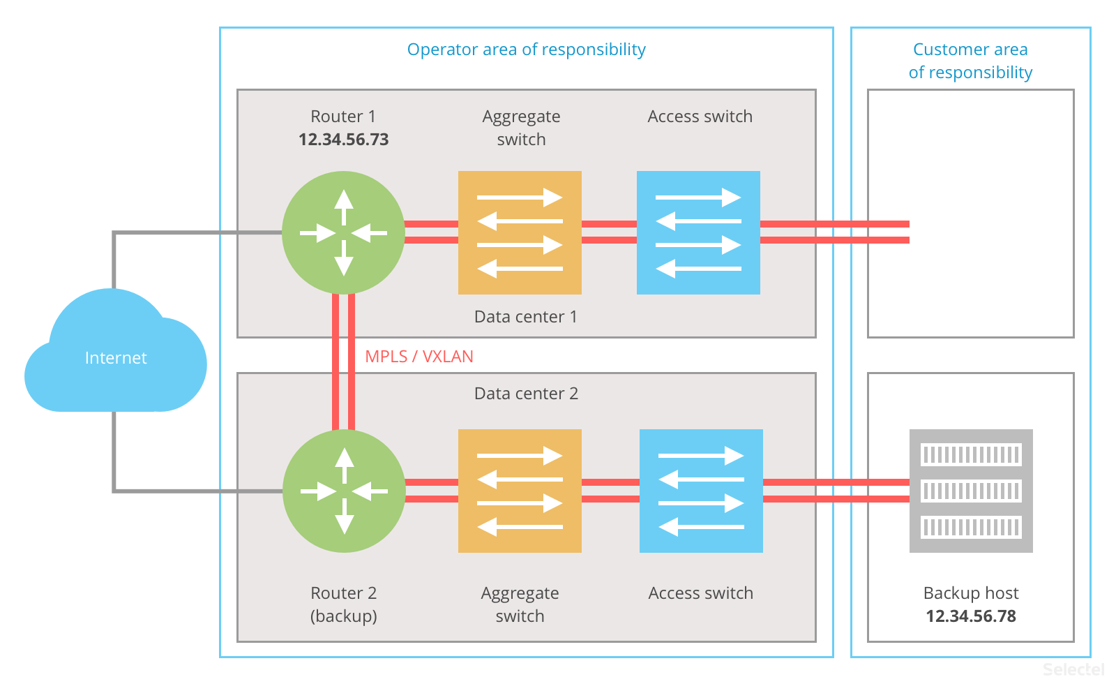
If .78 is the host address, then .73 is the default gateway address. This address is the operator’s responsibility, and if the host is located in the data center, then it is the data center’s responsibility. The following graph visualizes this structure:
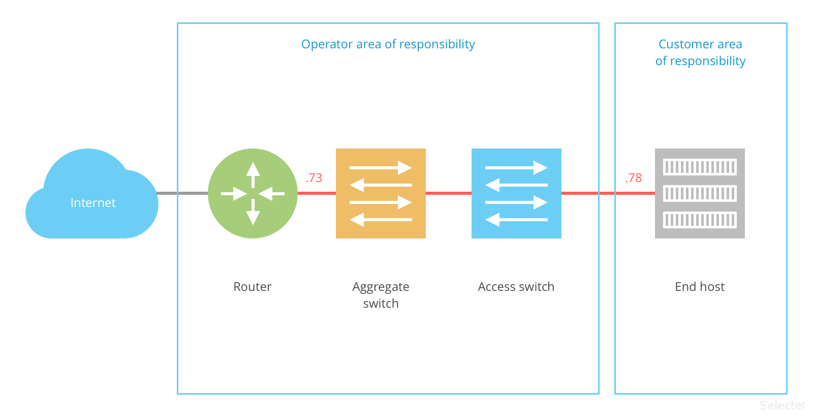
The end host is registered as 12.34.56.78 and the router as .73; a single L2 domain (oftentimes a single VLAN) is established between them:
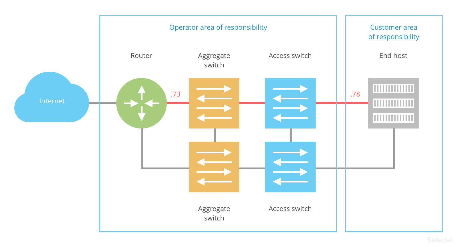
To raise the end host’s availability, a backup network infrastructure is required. The simplest way to achieve redundancy at the L2 level is by implementing Virtual Chassis/Fabric/MC-LAG. The end host is then connected to the data center’s network over LAG (Etherchannel):
The router and end host in this case are potential points of failure.
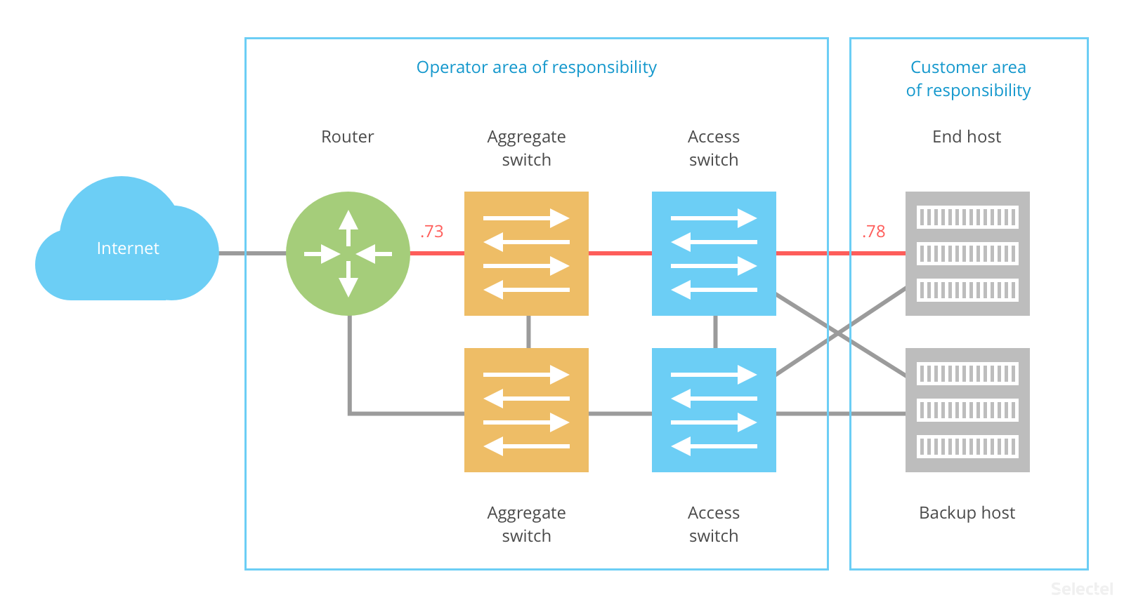
End host redundancy falls on the customer. Ideally, the end host and its backup would be located in different data centers. This would avoid a number of issues (with the network structure, the availability of the physical server, and the power supply, and cooling in separate areas).
There are different ways to transfer the IP address between the main and backup host. In one L2 segment, we can do this using CARP/HSRP/VRRP or similar protocols:
If we want full redundancy at the data center level, then we would have to back up every service component and ensure there is no single point of failure.
The ideal redundancy plan looks like this:
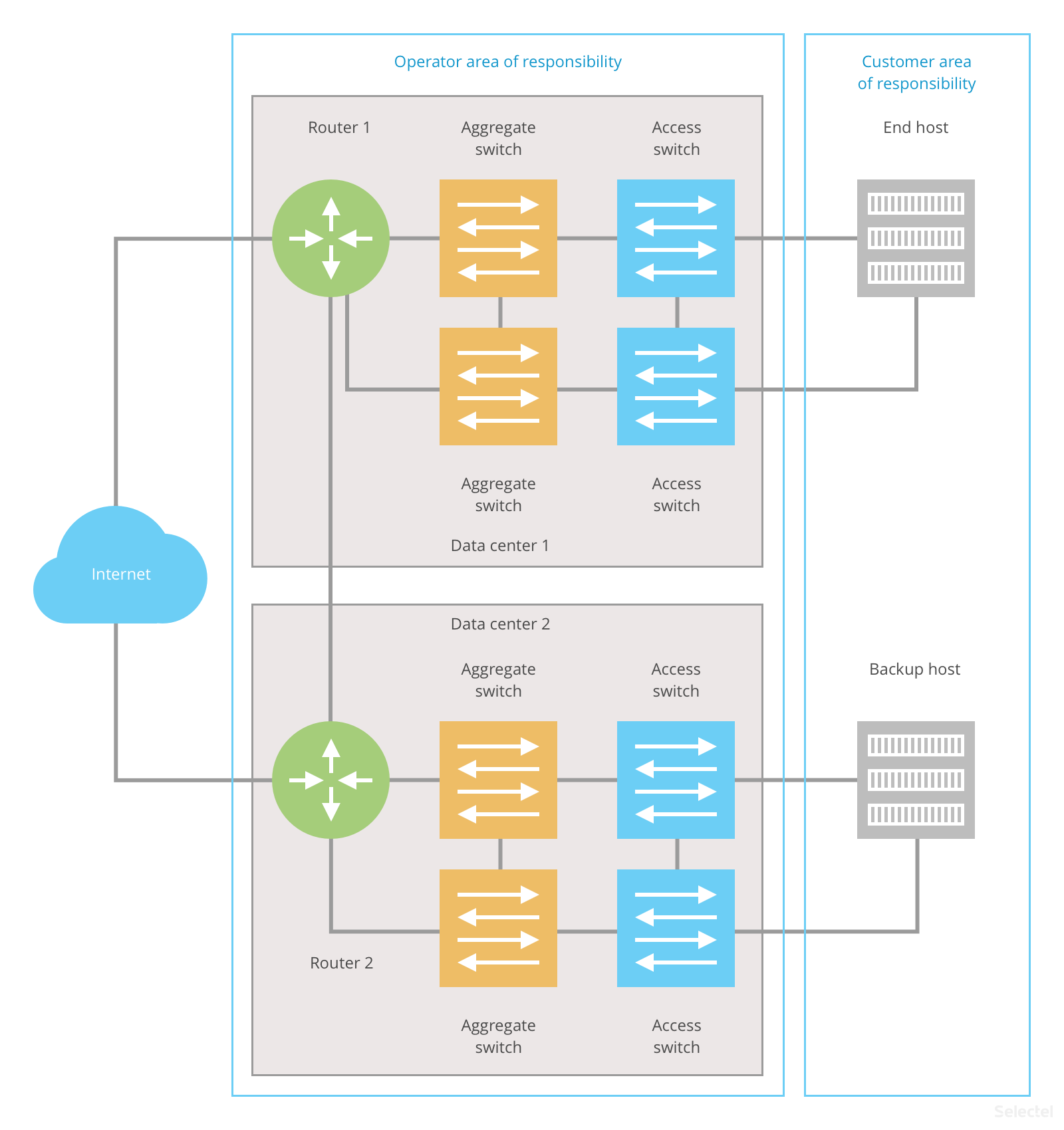
The customer’s end host and backup host are located in different data centers. The operator’s routers are also located in different data centers. These data centers may be connected by multiple communication channels.
If an error occurs in one data center, the end host will still be accessible. This approach can be used for both L2 and L3 schemes.
Router Redundancy
For an example of L3 redundancy, we can look at anycast routing and BGP connections to a higher operator. Each host announces 12.34.56.72/29 with different priorities on the operator’s router. In this case, each host connects to the router with a different subnet and VLAN:
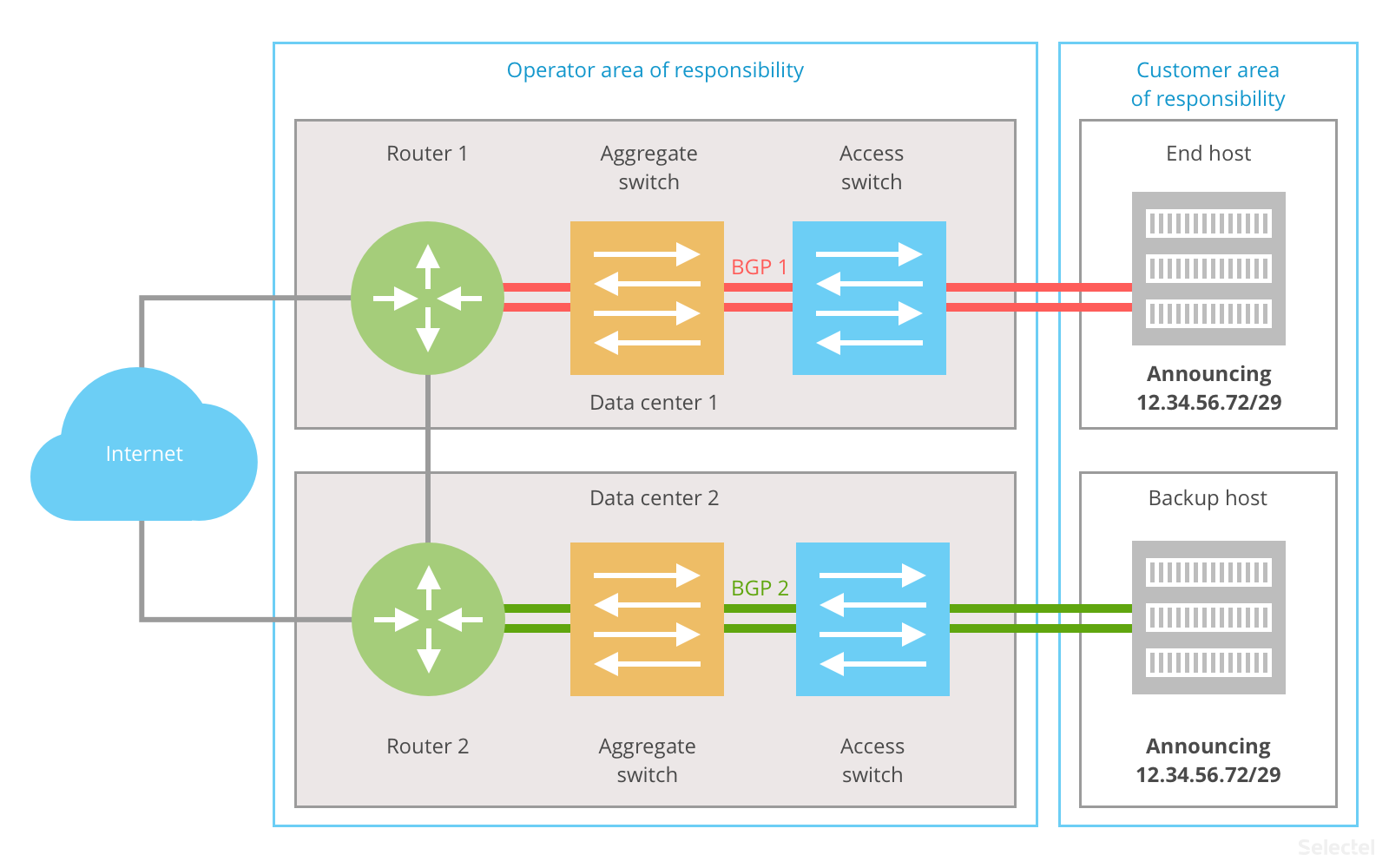
This scheme has the following advantages:
- it is widely used on the Internet (BGP);
- scaling is not for two, but several data centers.
Drawbacks include:
- low speed (typical BGP convergence time is at least 1.5 minutes);
- complicated setup;
- separate subnets must be assigned for each data center connection.
The time it takes to switch to the backup host can be reduced if instead of BGP, either OSPF or IS-IS protocols are used. The problem here is that not every operator lets you use these protocols: they are often used for transferring overhead data (like MPLS labels or secondary addresses), but they are capable of much more.
With an L2 scheme, the operator organizes a single L2 domain between the main and backup hosts. A VXLAN or MPLS tunnel is established between the routers:
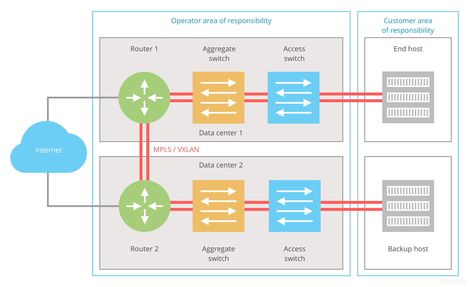
VXLAN/MPLS provides redundancy by using multiple communication channels between the ISP’s routers.
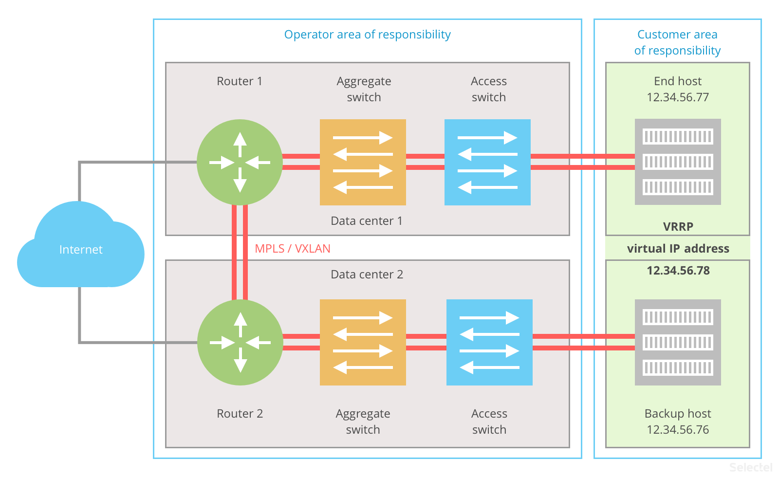
The end and backup host are connected to each other over VRRP or a similar protocol. This is how the active host registers IP address 12.34.56.78 (if both hosts are active, then it is registered on the master host). The end host receives its IP address–12.34.56.77–from this network, and the backup host gets its address–12.34.56.76–from the same network. If Windows has been installed on the hosts, then NLB clustering may be used in place of VRRP.
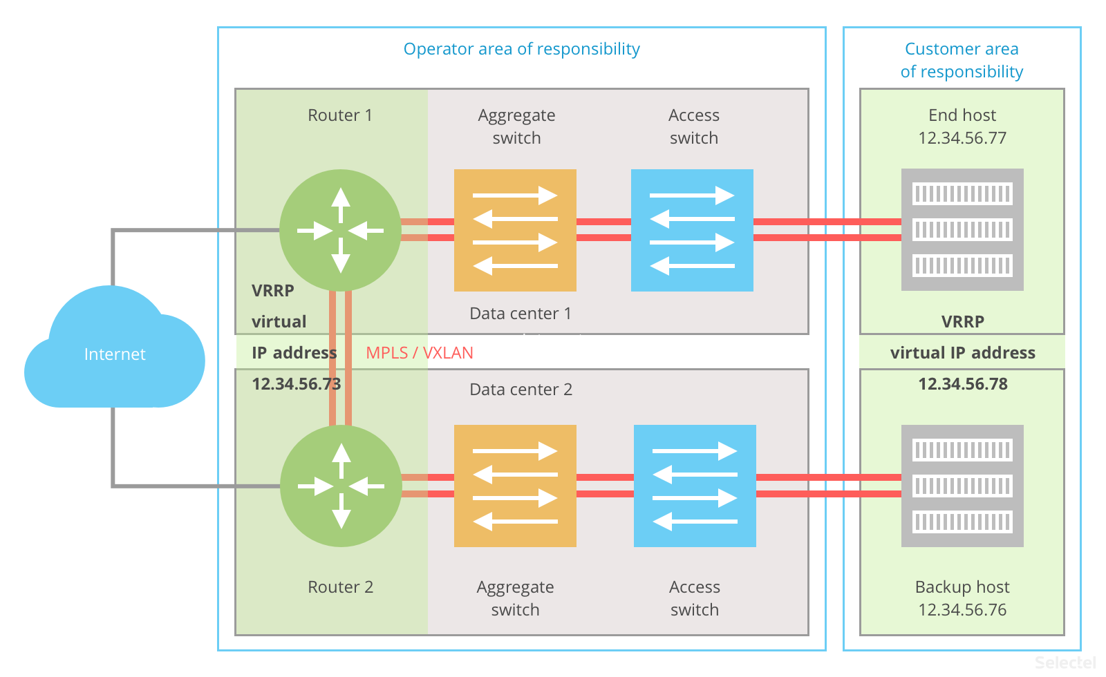
A similar plan is implemented on the operator side. Both routers take part in one VRRP domain and share the default gateway address 12.34.56.73/29. Router 1 has been configured as the master with the physical IP address 12.34.56.73, and router 2 has been configured as the backup rouer with physical address 12.34.56.74; 12.34.56.73 is a virtual address for this router and only actived when router 1 is unavailable.
The obvious advantages of this scheme are:
- use of standard protocols (VRRP);
- easy setup on the customer side and operator side;
- high-speed.
There’s only one drawback: it isn’t easy to scale to more than two data centers.
In Case of Emergency: How Does It Work
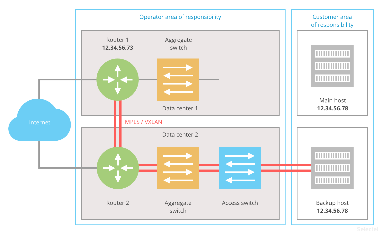
Normally, both routers and hosts work. When implementing the scheme, one router is named the primary (master) and answers 12.34.56.73. The same is true for hosts: one is named the primary host and responds to requests to 12.34.56.78. The second router and host are backup.
Internet requests pass through router 1 and are transferred to the primary end host.
The router has an ARP entry for 12.34.56.78 with MAC address 0000:5E00:01xx, indicating the route to the main host. The main host responds to Internet hosts by routing through router 1 (for hosts with the default gateway 12.34.56.73). To lower network latency, the primary router is placed in the same data center as the default host.
What happens when one of the hosts is unavailable? The VRRP on the backup host determines that the main host has stopped responding to keep-alive requests, and the IP address 12.34.56.78 is assumed by the backup host:
Internet requests are received on router 1, which sees the MAC address that corresponds to IP address 12.34.56.78 from router 2’s side and forwards traffic to the backup host. The backup host sends response traffic to default gateway 12.34.56.73, i.e. through router 1. With this scheme, latency rises between hosts on the Internet and the backup host.
After fixing the error, IP adress 12.34.56.78 will again be available for the primary host and the structure will work as it normally does.
Similarly, this layout works if the infrastructure between the router and end host goes down:
When the interconnect switches break down, the primary host keeps the address 12.34.56.78, but doesn’t have a network connection to the router and cannot process Internet requests. The backup host, having lost connectivity with the main host, assumes responsibility for the address 12.34.56.78.
If router 1, or all of data center 1 for that matter, becomes unavailable, the scheme will work exclusively through router 2 and the backup host:
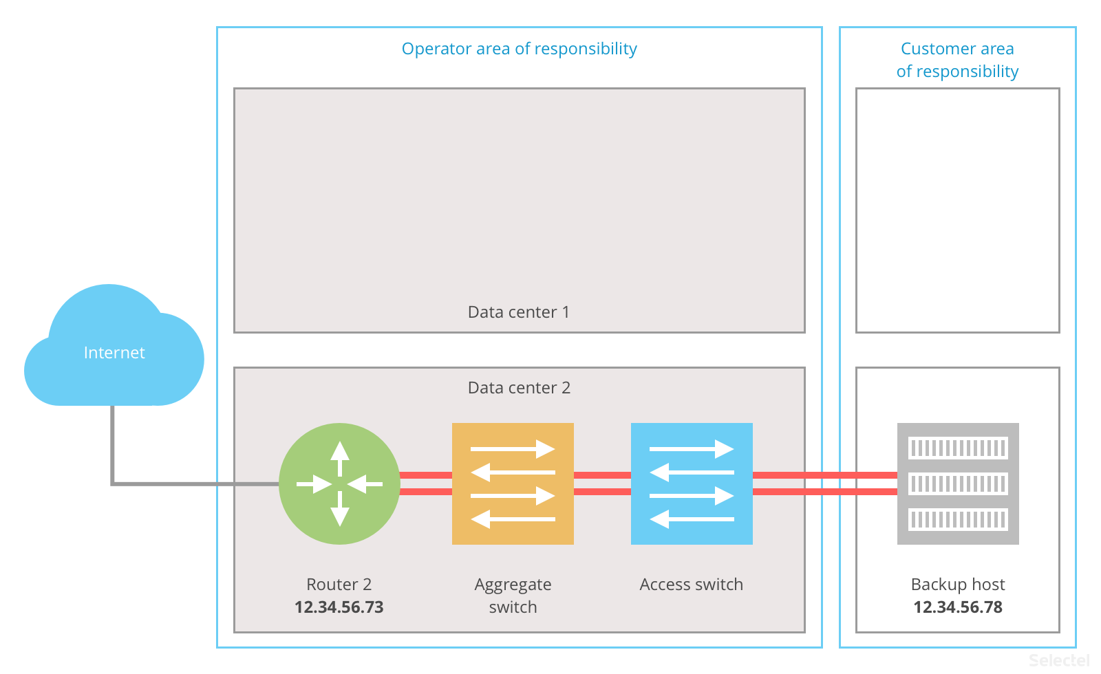
Once the infrastructure has been restored, operations will again run normally. Practically no breakdown in data center 2 influences the availability of the end host.
This solution allows commonly accessed resources to be installed and maintained, adequately backed up, and distributed among different data centers.
Conclusion
In this article, we looked at technology for backing up network connections via VRRP. This is a service we already offer. It was conceived primarily for major corporate clients looking to increase reliability and fault tolerance. The new service helps ensure uninterrupted availability for commonly accessed high-load resources.
A VRRP connection can be ordered from our control panel.